In any architectural project, walls are always one of the most fundamental and essential elements.
This article introduces the common types of walls in Archicad and provides a detailed guide on how to create them—from basic walls to advanced types such as Composite Walls, Curtain Walls, and Complex Profile Walls.
Wall Tool Archicad
In Archicad, you can model a wide variety of wall types:
Basic Wall: a single-layer wall, simple and quick to use.
Composite Wall: multi-layer walls with different materials (e.g., brick, mortar, insulation).
Complex Profile Wall: custom-shaped walls with unique profiles.
Curtain Wall: modular glazed systems, created using a separate Curtain Wall Tool instead of the Wall Tool.
Some Archicad elements can only be placed on walls, such as doors, windows, and wall ends.
All wall parameters are managed in the Wall Tool Settings dialog.
Types of Walls in Archicad
In Archicad, there are many different types of walls for design needs.
- Basic Wall : A simple wall consisting of a single material layer. Typically used for quick massing models or projects requiring a low level of detail (LOD).

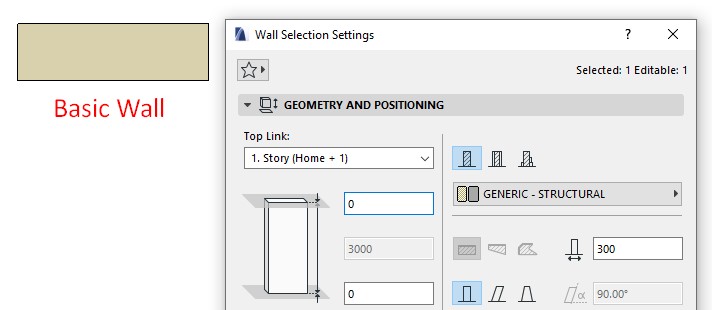
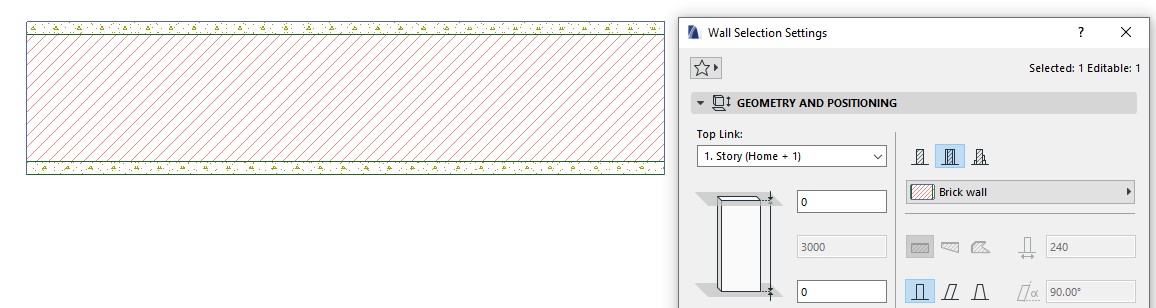
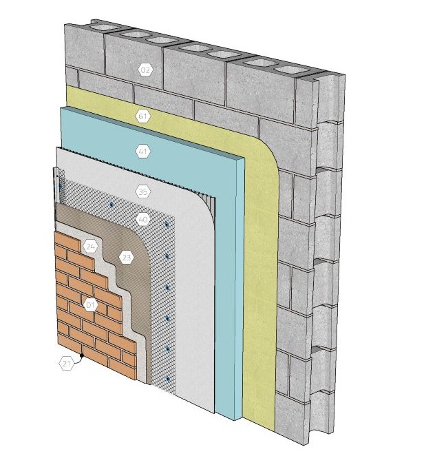
- Composite Wall: A wall made up of multiple material layers (e.g., brick + plaster + insulation).
For example: a composite wall with one brick layer and two plaster layers.

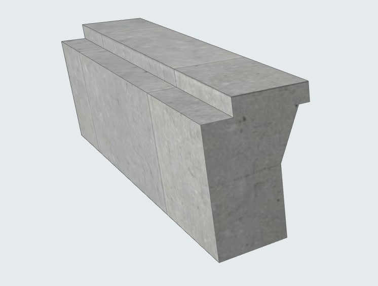
- Complex Profile: Walls with custom profiles and non-standard shapes.
For example: a wall section designed with a special profile.
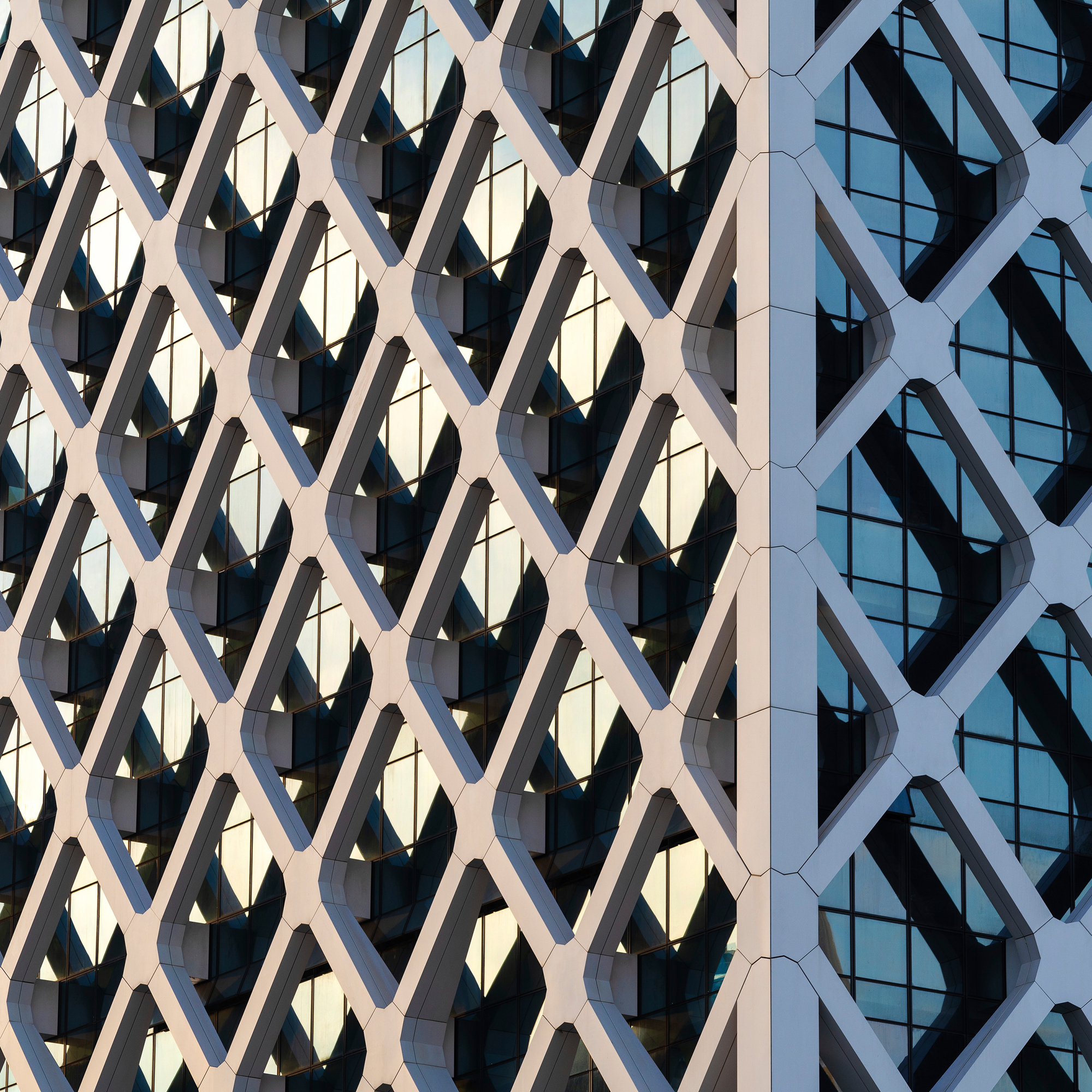
- Curtain Wall: Modular facade systems, typically used for glazed facades, showrooms, or office buildings.
These are created with the Curtain Wall Tool, not the Wall Tool.
How to Draw Walls in Archicad
To start creating walls in Archicad:
Select the Wall Tool from the Toolbox.
Open the Wall Tool Settings (Ctrl + T) to configure parameters.
Choose a Geometry Method and draw walls directly in the workspace.
Archicad offers several drawing methods:Straight Wall, Chain Wall, Curved Wall, Trapezoid Wall, Polygon Wall.

Straight Wall
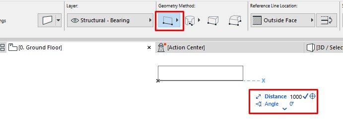
Select the Wall Tool → Click start point → Click end point.
Or press Tab to input an exact length in the Distance field.
Chain Wall
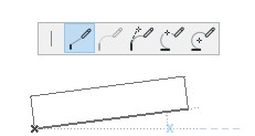
Use this method to draw multiple segments in one go.

Options in the pet palette allow:
Straight segment
Tangential arc
Arc through two points
Arc by center, radius, and chord length
Double-click to finish. Press Backspace to undo the last segment.
Curved Wall
Three input methods are available:

- By center point and radius
- By arc through three points
- By tangent references
Note: tangent method is only available in floor plan view.
Trapezoid Wall
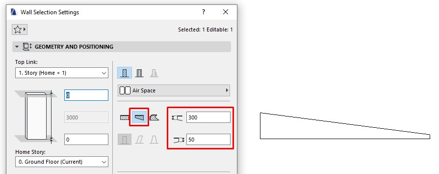
Used when wall thickness differs at each end.

Simply set start thickness and end thickness in the settings.
Polygon Wall
Draw custom polygonal walls, useful for irregular footprints.
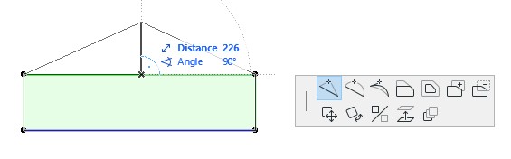
Windows and doors can still be inserted, but Complex Profiles cannot be applied.

After selecting a polygonal wall, draw the border of the wall. After clicking the first point, the Palette optional table will appear with straight or curves drawing modes, similar to the time when drawing the wall (chain wall).
You can also convert a normal wall into a polygonal wall by choosing a wall, then selecting Polygon Wall in the wall setting.
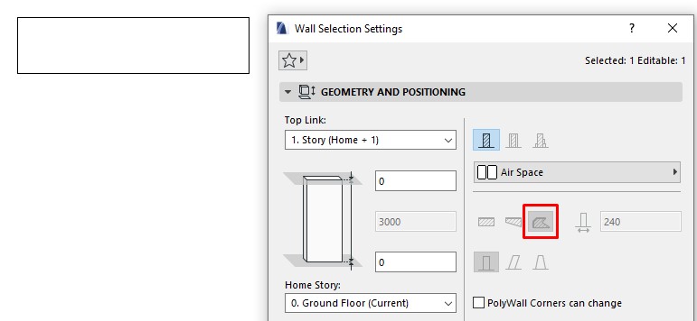
After converting into a polygonal wall, click on the wall and select custom commands on the palette to edit the wall shape.
Working with Composite Walls
Composite Walls allow you to define multiple material layers.
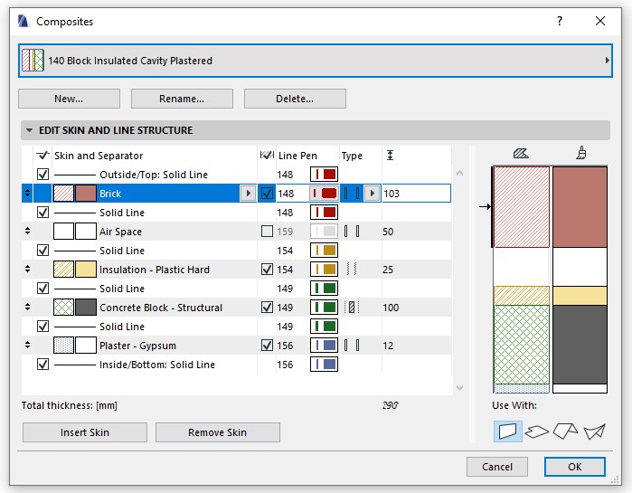
To manage composites:
Go to Options > Element Attributes > Composites…
Create new or edit existing composites by adjusting thickness, materials, and order of layers.
Composite structures are essential for projects requiring high LOD and detailed material breakdown.
Note: composites can also be applied to slabs, roofs, and shells.
Wall Reference Line
One of the most overlooked but crucial aspects of working with walls in Archicad is the Reference Line.
This is the baseline Archicad uses to place and manage walls.
Reference Lines are invisible in drawings but control intersections, corner connections, attributes, and zone area calculations.
Correct use of Reference Lines ensures accurate modeling and prevents issues when adjusting wall thickness later.
Show Reference Lines: View > On-Screen View Options > Walls & Beams Reference Lines
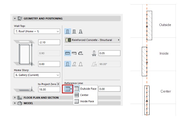
Reference Line in Basic Walls
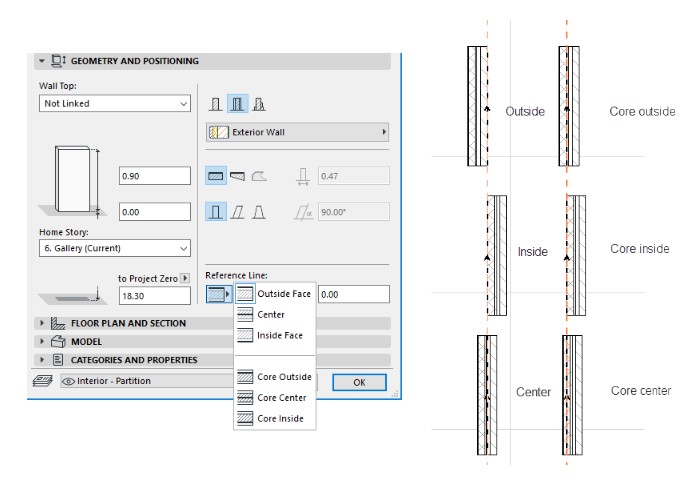
A basic Wall has three possible reference lines: running along the outside face, inside face, or the center.
By default, the reference line runs along the “outside face”.
Reference Line in Composite Walls
A composite Wall has six possible reference lines: outside/inside/center of the Wall, plus outside/inside/center of the Wall core.
Note: If the chosen composite structure has no core, then the core-related Reference Line choices are grayed out.
By default, the reference line runs along the “outside face”.
For a composite, the “outside” surface is the first listed skin of the composite, in Composite Settings.
Reference Line in Trapezoid Walls
A Trapezoid wall has two possible reference line locations: Outside Face or Core Outside (if it has a core).
Reference Line in Polygon Walls
Reference line controls in Wall Settings do not apply to Polygon walls. (Polygon wall reference lines can be moved graphically via the pet palette.)
Reference Line in Complex Profile Walls
The reference line of a Profile (complex) wall depends on the user origin defined in Profile Manager/Editor.
Reference Line Offset: If using an “outside” or “inside” reference line, enter a positive offset to move the reference line toward the center (or center of core) of the Wall. A negative offset will move the reference line away from the center (or core center). (No offset is available if the reference line is in the center.)
As you adjust the reference line location, notice that the body of the Wall moves laterally. The reference line stays in place.
Note: In contrast, to move the reference line while retaining the Wall’s position intact, and/or mirror the openings, use the Modify Wall Reference Line command.
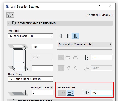
Reference Lines are typically set to centerline or core centerline, but choice depends on design intent.
Wall Display Settings
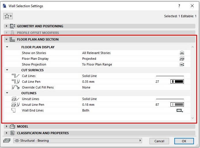
Wall Floor Plan and Section Panel
Installation of wall display on the ground and cross section in the Panel Floor Plan and Section
Floor Plan Display
- Show on Stories: Choose an option to define which stories will display the wall.
– All Relevant Stories: A multi-story wall will be displayed and editable on all stories which it intersects. Multi-story walls will be correctly joined with other elements on all stories where the multi-story wall is present.
– Home Story Only: This wall will be displayed only on its Home Story. - Floor Plan Display:Choose an option to define the Wall’s display on the Floor Plan.
– Projected: shows cut part of Wall’s 3D model, plus its uncut (downward) part.
– Projected with Overhead: shows cut part of Wall’s 3D model (i.e. as cut at the level of the Floor Plan Cut Plane), plus the Wall’s overhead part (i.e. the part of the Wall that is above the Floor Plan Cut Plane.
– Cut Only: displays only the cut part, as cut with the Floor Plan Cut Plane. - Show Projection:This pop-up contains three options. (These are available only when the Floor Plan Display option is set to one of the “Projected” options.)
– To Floor Plan Range: Choose to show the Wall on a range of stories (the current story, plus a given number of stories above and below it.)
Note: If you choose this option, then you can set the desired range (i.e. the number of stories on which to show this Wall in either direction) in Floor Plan Cut Plane Settings.
– To Absolute Display Limit: Set a fixed lower limit (by default, this is Project Zero), then show all parts of the Wall above this limit.
Note: If you choose this option, go to Floor Plan Cut Plane Settings to set the Absolute Display Limit.
– Entire Element: The Wall will be displayed on all relevant stories.
Cut Surface
In this section, set the attributes displayed for cut surfaces both in Section and on the Floor Plan.
- For a basic Wall: Define the cut line type and pen
- For a basic, composite or complex profile Wall: If needed, override the fill foreground/background pens of this element (defined by default in the Building Material). To do this, choose Foreground, Background or Both from the Override Cut Fill Pens pop-up to access the respective controls.
Outlines
Use these settings to define line types and pen colors to element outlines that fall above (Overhead) and/or below (Uncut) the Floor Plan Cut Plane.
- Overhead Lines will be displayed if the Floor Plan Display pop-up is set to “Projected with Overhead” or “Overhead All”.
- Uncut Lines will be displayed if the Floor Plan Display pop-up is set to “Projected” or “Outlines Only.”
- Wall End Lines: This pop-up gives you four ways to display a freestanding wall on the Floor Plan. The options let you show or hide one or both end lines of the wall. (The end line is the contour line perpendicular to the longitudinal axis of the wall.)
Wall Model Panel
This panel affects the 3D display of the wall.
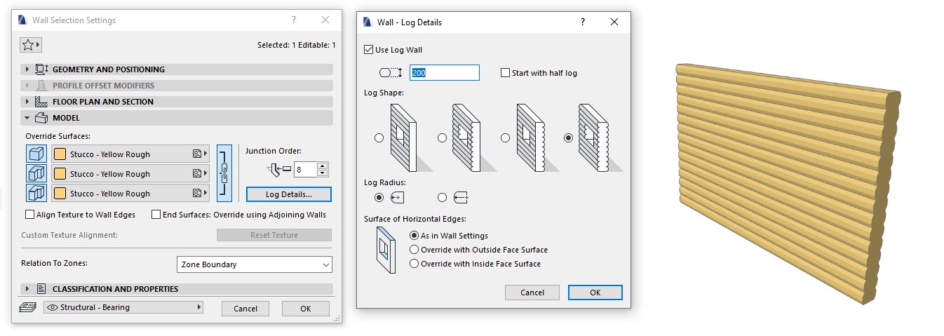
- Override Surfaces: Click the toggle button of any or all three pop-ups if you wish to override the surface assigned to this element (in its Building Material). You can override the surfaces of the Wall’s faces (outside and inside), and/or all Wall edges.
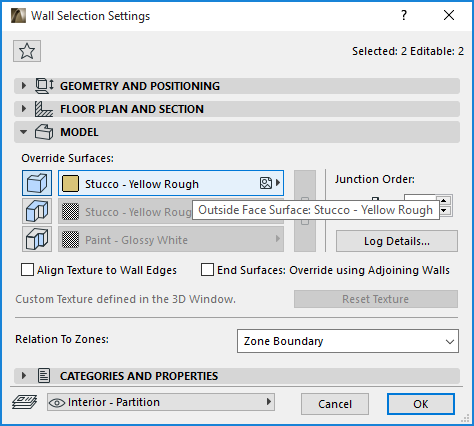
- Align Texture to Wall Edges: Check this box to place the texture origin at the bottom corner of the wall. This can be useful, for example, on freestanding walls to avoid a fragmented texture on the edges.
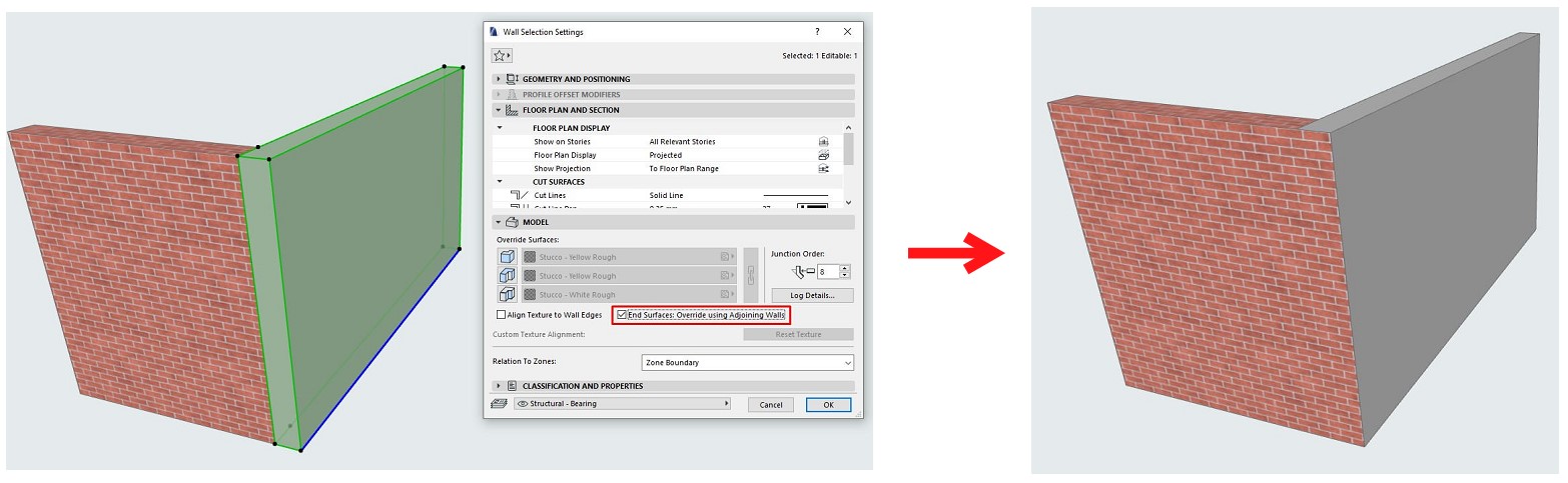
- End Surfaces: Override using Adjoining Walls: Check this box if you want the selected Wall’s end surface to take on the surface of the adjoining Wall.
Note: Any adjustments to the surface texture alignment will be correctly reflected on both walls.

Create a Log Wall
You can create straight walls constructed from logs. Log details appear in both the 3D Window and Section/Elevation/IE Windows.
Clicking the Log Details button in the Model panel of Wall Settings provides a number of geometry and texture options.
Note: Log construction is only available for basic straight walls. When determining the log’s height, remember that if you enter a value that is larger than the wall’s width parameter, the logs will not rest on each other.