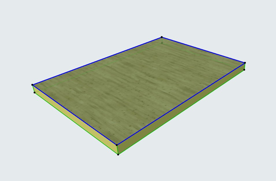
Slab Tool – The tool used to draw and edit floors and horizontal structural elements in Archicad.
Slab Tool Settings
Similar to other tools introduced in previous lessons, to open the Slab Tool Settings, select the Slab Tool from the Toolbox and press Ctrl + T (or double-click the Slab icon).
|See: Getting Started With the Archicad Interface
Geomotry and Positioning
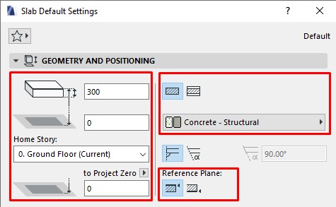
Slab Thickness:Enter the value for the slab thickness.
Note: If the slab structure is a Composite, its thickness will be defined in the Composite Settings
(Options > Element Attributes > Composites).
In this case, to change the slab thickness, edit it in the Composite settings or switch to a basic slab type to input a manual thickness.
Offset to Home Story: Enter the offset value from the Home Story level to the Reference Plane of the slab.
Home Story: Select the story level where the slab element will be located.
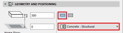
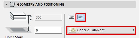
Slab Structure: Choose one of the two icons to define the slab type — Basic Slab or Composite Slab.
- For Basic Slab, select the icon and then assign a surface material.

- For Composite Slab, select the icon and choose a composite structure.
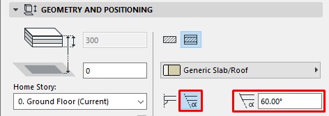
Slab Edge Angle: By default, slab edges are perpendicular (90°) to the surface. To customize, select the icon on the right and enter the desired angle value.
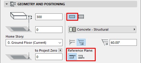
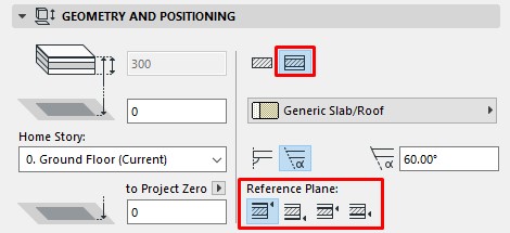
Reference Plane: Depending on whether the slab is basic or composite, there will be different reference plane options.
- Basic Slab: Top surface or bottom surface.

- Composite Slab: Top surface, bottom surface, top of the core, or bottom of the core.

Floor Plan and Section
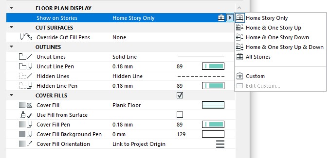
Show on Stories: Select which stories the slab will be visible on — either Home Story only or multiple stories.
Outlines: Define the line type and pen color for the slab’s outline.
Cover Fills: If you want the slab to display a hatch pattern, check Cover Fills and select the Fill Type and Pen color.
Slab Model Panel
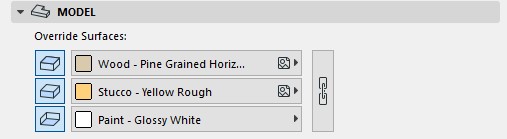
Check the surfaces of the slab where you want to override the material, then select a surface material for each face.
You can also click the chain icon to apply one single material to all slab surfaces.
Creating a Slab Model
Follow these steps to create a simple slab model:
- Select the Slab Tool from the Toolbox.
- Double-click the Slab icon or press Ctrl + T to open the Slab Tool Settings.
- Configure the required parameters as described above, then click OK.
- In the Geometry Method panel, choose a drawing mode that fits your need: polygon, rectangle, or rotated rectangle.

- For Polygon mode: Click each vertex of the polygon, then right-click and choose OK to finish (or click again on the first point to close the polygon).
For Rectangle mode: Click to set the first corner, move your cursor to define the rectangle shape (or press Tab to enter exact dimensions), and click again to complete.
For Rotated Rectangle mode: Click points 1 and 2 to define one edge, then click again to complete the second edge of the rectangle.

Creating Openings in a Slab
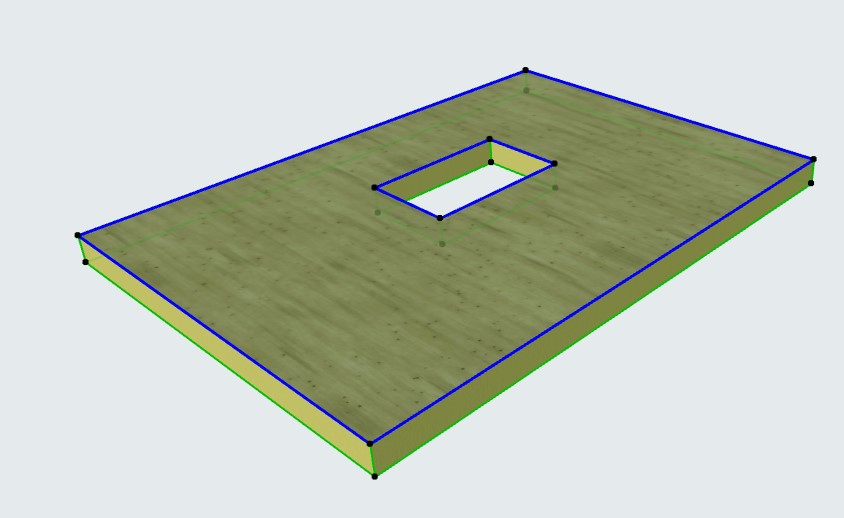
After creating the slab, you may need to create openings for elements like stairs, elevators, or shafts.
Follow these steps to create an opening in the slab:
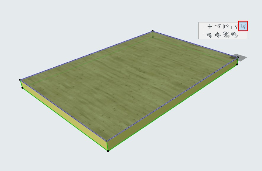
- Select the slab model.

- Click any point or edge of the slab, then select the minus “–” icon.
- Draw the boundary of the opening you want to create.

- Finish