In Archicad, there are 2 ways to create a Grid for a project.
Method 1: Using Grid System
Open the Grid System settings panel via Design > Grid System.
Grid System General Settings Panel

Here you can set up the basic configuration of the grid system:
- Geometry: Choose between a straight grid system or a curved one. If you select a curved grid, enter the radius value in the box on the right.
- Place…: Tick the boxes for any elements you want to place automatically at grid intersections.
– Elements at Grid line intersections: Add objects at the grid intersections. Select the object from the panel and click Settings… to define its parameters.
– Default Beams on Grid lines: Place beams along grid lines. Click Settings… to define beam properties.
Note: If the grid system is curved, you can choose either straight or curved beams to follow the grid lines.
– Dimension lines: Add dimension lines between grids. Enter the offset distance and label placement. Click Settings… for more options.
– Total Dimension: Add the overall dimension of the entire grid system. Similar settings apply.
Tip: Use the “chain link” icon to synchronize both dimension settings. - Keep Column and/or Beam within Grid perimeter:Tick this option to align outermost columns/beams with the grid boundary.
Grid System Grid Elements Panel

- Grid Element Settings: Define properties for all grid lines in this system.
- Extension: Set the offset distance for grid labels beyond the outermost line.
- Anchor: Define the anchor point (base point) for the grid system placement.
- Markers: Choose the sides where grid labels should appear (one or multiple).
- Auto-stagger Grid Markers if they overlap: Enable this so grid markers rearrange automatically when overlapping.
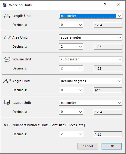
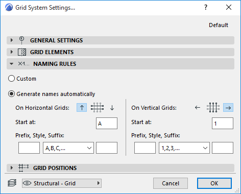
Grid System Naming Rules Panel

This tab lets you set up naming rules for grid lines.
For circular or radial grids, naming conventions for horizontal and vertical lines depend on their placement.
- Custom: Manually name each grid line.

- Generate names automatically: Automatically generate names based on rules.
- Ascending direction: Define the naming direction by selecting the up/down or left/right arrow.
Grid System Grid Positions Panel
This section defines the number of grid lines and their spacing.

- Use the “+” or “–” buttons to increase or decrease the number of horizontal/vertical grids.
- Enter spacing values into the Distance field.
- Distribute: If you don’t want to enter exact distances, select this option to distribute spacing evenly.
Method 2: Using the Grid Tool
If you don’t want to use the Grid System, you can create grids manually with the Grid Tool in the Toolbox.
![]()
With the Grid Tool, you can only place grids individually. However, it is more flexible for local or complex layouts that cannot be customized within the Grid System.
Grids can be placed in the Floor Plan or 3D Window views, and you can also configure them to appear in Elevations and Sections.

Grid displayed in Floor Plan

Grid displayed in 3D