After exploring the Wall Tool in the previous lesson, let’s move on to another essential building component that always goes hand in hand with walls: the Door and Window Tools.
In Archicad, doors and windows are designed to replicate their real-life appearance and behavior. They are always placed inside walls, never as standalone elements. Since the setup and modeling process for doors and windows are almost identical, we’ll cover both tools together in this guide.
Door/Window Tool Settings
The library of available doors and windows, as well as their detailed settings, will vary depending on the library set you are using.
For this tutorial, we are working with the International Version of Archicad, which comes with its default library. If you are using a localized language version or third-party libraries, the available options and settings may differ significantly.

Preview and Positioning
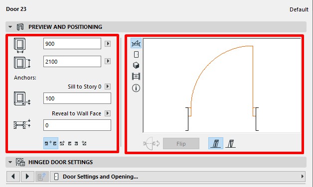
In the Preview and Positioning panel, you can configure the width, height, and placement of the selected door or window.
On the right side of the panel, you’ll find preview windows that display the door or window in floor plan, elevation, and 3D views. This helps you visualize exactly how the element will appear in different drawing modes. Simply click through each preview option to check the display.
The layout and functionality of the Preview and Positioning panel are almost identical across all doors and windows, regardless of the library you are using. This consistency makes it easier to learn and apply the tool, no matter the project or library set.
Custom Settings
The Custom Settings panel allows you to fine-tune the appearance and parameters of your selected door or window. Depending on the library object, this panel may appear under a different name.
For example, in the case of a hinged door, the panel is labeled “Hinged Door Settings”

Just below the panel title, you’ll find tabs that contain customizable parameters such as frame type, handle style, sash configuration, and glazing details. Use the arrow buttons to navigate between tabs and adjust settings as needed.
Each adjustment is supported by a visual preview, making it much easier to understand what effect your changes will have on the object.
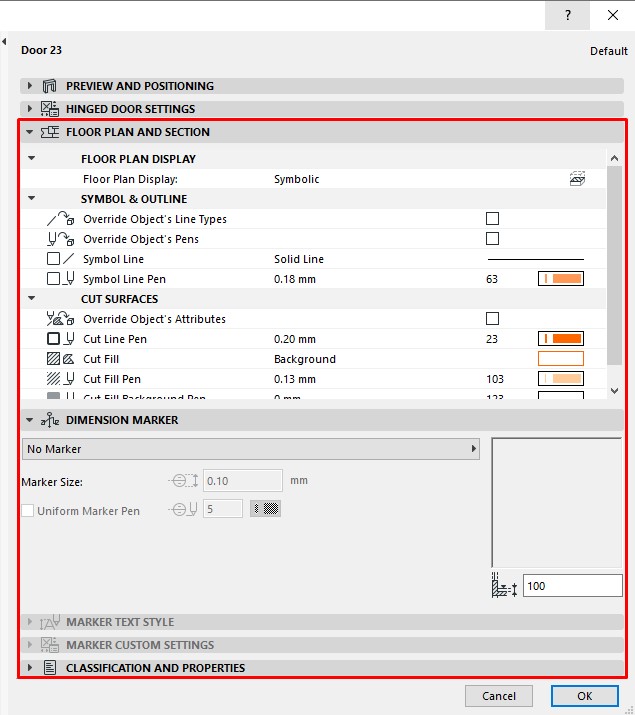
In addition, the Door/Window Settings dialog also includes options related to:
- Floor plan and section representation
- Custom tags and labels
- Symbolic display parameters
However, for beginners, it is enough to focus on basic size and shape settings. The more advanced display and tag customizations can be explored later, once you are comfortable with the fundamentals.
Model Door/Window
Doors and windows can only be placed into walls. They cannot exist as standalone models within your project.
Follow these steps to insert a door or window:
- In Floor Plan view or 3D view, select the Door Tool or Window Tool from the Toolbox. Choose the type of door or window you want from the library.
- Move your cursor over the wall where you want to place the element. A preview outline will appear at the intended location.

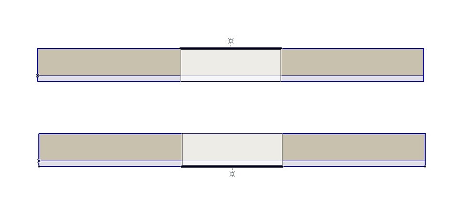
- Additionally, when hovering over a wall, you will see a sun icon and a bold reference line. These indicate the exterior face of the wall.
To switch the exterior side, simply move your cursor back and forth across the two sides of the wall and click on the side you want to define as the exterior. - Click to place the door or window in the desired position.
Use the Anchor Point option to decide whether the element is positioned by its center point or by one of its edges.

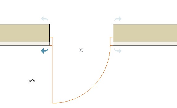
- Next, you will choose the opening direction: toward the inside or outside of the wall, either on the right or the left: each possibility is shown by an arrow on screen.
Move the cursor around to any of these four positions; the feedback shows you what you will get when you click.
- Click to place the opening.

Flip Opening Direction
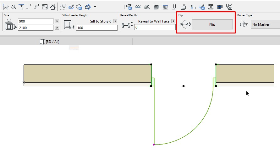
After placement, you may realize the swing direction is not what you wanted. Instead of deleting and re-placing the element, you can use the Flip command to quickly invert the opening direction.
It only changes the swing direction. The frame position and other settings remain unchanged.
This feature saves time and ensures that your modeling workflow remains efficient.